Soft Shadow Maps for Linear Lights
    |
Soft shadows and penumbra regions generated by extended light sources such as linear and area lights are visual effects that significantly contribute to the realism of a scene. In interactive applications, shadow computations are mostly performed by either the shadow volume or the shadow map algorithm. Variants of these methods for soft shadows exist, but they require a significant number of samples on the light source, thereby dramatically increasing rendering times.In this paper we present a modification to the shadow map algorithm that allows us to render soft shadows for linear light sources of a high visual fidelity with a very small number of light source samples. This algorithm is well suited for both software and hardware rendering.
We introduce a new soft shadow algorithm based on the shadow map technique. This method is designed to produce high quality penumbra regions for linear light sources with a very small number of light source samples. It is not an exact method and will produce artifacts if the light source is so severely undersampled that the visibility information is insufficient (i.e. if there are some portions of the scene that should be in the penumbra, but are not seen by any of the light source samples). However, it produces believable soft shadows as long as the sampling is good enough to avoid these problems.
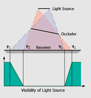
This setup is illustrated in the figure on the left. Given a linear light source and one occluder and receiver polygon, the resulting shadow will consist of two penumbra regions (between p1/p2 and q1/q2) and one umbra region in the center (p2 to q2). The visibility term (green) we would like to approximate is sketched below. Starting at 100% at the left (p1), visibility drops down to 0% at the beginning of the umbra region (p2) and then raises up to 100% between q2 and q1.
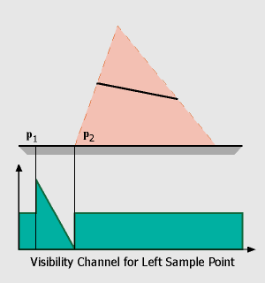
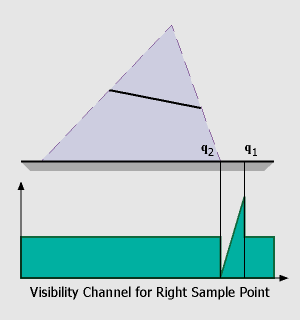
In the first step, we have to compute the regions in which penumbra and umbra regions can occur. This is done using the standard shadow map algorithm. In our simple setup, we consider the endpoints of the linear light as two distinct point light sources and render shadow maps as seen from these sample points. This results in two hard shadow regions, one from p1 to q2 (bright blue) which belongs to the right sample point, and one from p2 to q1 (orange) belonging to the left sample of the linear light source.
In the next step we must determine the visibility function. It is obvious that for completely lit and shadowed (umbra)
regions the information in the shadow maps is sufficient. A point is completely lit if it can be seen from both sample points
whereas a point is in the umbra if it cannot be seen by either the left or the right sample point. For these regions we use
a default value of 0.5 for the visibility channel (the reason for this will be explained later).For the raise and fall of the visibility (p1 to p2, q2 to q1) we have to do a little more work: In the figure on the left, it can be seen that the 'fall off' region is determined by the relative positions of the receiver, the left side of the occluder and the two sample points. We can compute this region by finding the depth discontinuities in the shadow map belonging to the right sample point, triangulating these values and warping the resulting triangles to the view of the left sample point. These skin polygons have the characteristic that they connect an occluder edge with a receiver edge. Projecting these polygons onto the receiver polygon is easy because we can use graphics hardware for this step: First we render the first channel of both shadow maps (depth values), then we compute the skin polygons, warp them to the opposite view (sample point) and render them with the z-buffer algorithm. The 'fall off' and 'raise' of the visibility function can also be integrated in this step if we assign a color value of '0' (black) to vertices on the occluder edge and a color value of '1' (white) to vertices on the receiver. With Gouraud-Shading enabled, color values will be interpolated across the triangle, resulting in the desired visibility function (encoded in one of the RGB-channel of the framebuffer).
Now that we got two channels in each shadow map (depth values S1/2 and visibility values V1/2) the shading of a point p becomes easy:
shade(p) {
 if( depth1(p) > S1[p] )
   l1 = 0;
 else
   l1 = V1[p] * localIllum(p,L1);

 if( depth2(p) > S2[p] )
   l2 = 0;
 else
   l2 = V2[p] * localIllum(p,L2);

 return l1 + l2;
}
In this piece of pseudo-code it becomes clear that we need to initialize the visibility channel to a default value of 0.5 to sum up to 1.0 for complete lit regions (for umbra regions the visibility channel isn't used anyway).
W. Heidrich, S. Brabec, and H.-P. Seidel, Soft Shadow Maps for Linear Lights
Proceedings of the EG Rendering Workshop 2000.


